I’d like to keep these instructions up-to-date. If you discover a broken link in here, or something is no longer true (e.g. the lack of an open toolchain) please let me know!
A few years back I became interested in hobby electronics, but never made the time to do as much of it as a really wanted. One device I acquired and used very little was a Mojo v3 FPGA dev board. I recently had cause to become interested in FPGAs again, and dug it out to see what I could remember, and found that the state of support in 2024 is pretty poor: the board itself is discontinued, and its owner (rebranded Alchitry) doesn’t appear to be interested in maintaining the instructions for it. If you google “mojo v3 dev board” the third result is this dead link. This is unfortunate, because I suspect there are a lot of people who still own one of these boards and have written them off as abandonware.
The good news is that the Mojo is still perfectly usable in 2024, and I’m going to guide you through how to do so. These instructions are written for Linux, but they should work on Windows or a Mac with very little modification.
What is this board, why would I want one?
You can skip this section if you are holding a Mojo v3 and just want to be able to use the damn thing.
The Mojo is a dev board for an Spartan-6 FPGA. An FPGA is a configurable integrated circuit that lets you ‘wire up’1 arbitrary combinations of logic gates, within the size limits of the particular FPGA. Common uses are building devices that run highly parallel operations, custom CPUs (or clones of other CPUs), or extremely high-speed devices (e.g. software-defined radios). Even if the thing you’re building will be built in such volume that having ASICs made is cost-effective, you will want to prototype it, and FPGAs provide a way to do that.
You can’t just wire up an FPGA straight to your PC, it needs various support circuitry around it, e.g. a way to talk to a PC over a serial connection. You could design all of this yourself, but you’d have to have a PCB built and do some very tricky soldering - much better to use an off-the-shelf board that has the IO pins conveniently broken out, plus a few LEDs for quick testing.
Great, where can I buy one of these things?
You probably shouldn’t.
You can find them for sale on AliExpress, but the price is very similar to Alchitry’s new, and still supported,2 Au board (and higher than the Cu board). These newer boards have open source tool chains available too!
These instructions are intended for anyone who still has a Mojo sitting around and wants to use it, or gets one cheap.
Overview
These instructions will take you through setting up these three things and using them to load a simple design onto the Mojo:
- Xilinx ISE.
- Mojo template project.
- A ‘loader’ to transfer our design to the FPGA.
Installing the Xilinx ISE
An FPGA is configured by having a ‘bitstream’ read into it, which you can think of as the FPGA equivalent of a compile program. To create this bitstream we’ll need a proprietary piece of software from Xilinx called the Integrated Synthesis Environment (ISE). Xilinx are the company that make the actual FPGA on the Mojo, a ‘Spartan-6’. For there Spartan-7 FPGAs there is an open source toolchain, but not for the Spartan-6, hence our requirement to install the ISE.3
A lot of older tutorials have broken links for the ISE4, but you can find it here. You want version 14.7, and there will be four files to download, and the links should look like this (they’ll prompt you to create / log into an AMD account):
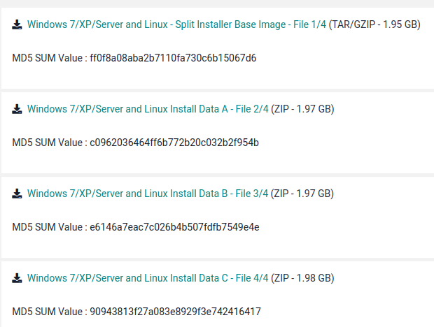
Download all 4 installation files (roughly 8GB in total), un-tar the first one, and run xsetup.
You should be prompted for the location of the other 3 files.
When the installation completes you will be prompted to add the line
source /opt/Xilinx/14.7/ISE_DS/settings64.sh >> /dev/nullto your profile. I found that caused problems, so I removed it. I now just start the ISE each time with
/opt/Xilinx/14.7/ISE_DS/ISE/bin/lin64/iseYou might want to add an alias for that to your .bashrc.
On first starting the ISE you’ll be prompted to obtain a licence, and the ISE will give you a link to the AMD site. You want the ISE WebPACK Licence - it’s free, thought you will need to give details to declare that you are not in a country subject to US export restrictions.
Get the Mojo Template Project and Write Some Verilog
We need to give the ISE a bit more information to begin writing the hardware configuration for our FPGA. I’m going to be honest, I don’t understand everything in here, but I have gotten it to work. The simple solution is to start from the a base project that already includes all of the boilerplate.
You can get this from the embedded micro git repo. Given the fact that the Mojo seems somewhat abandoned, I’ve also forked this repo here.
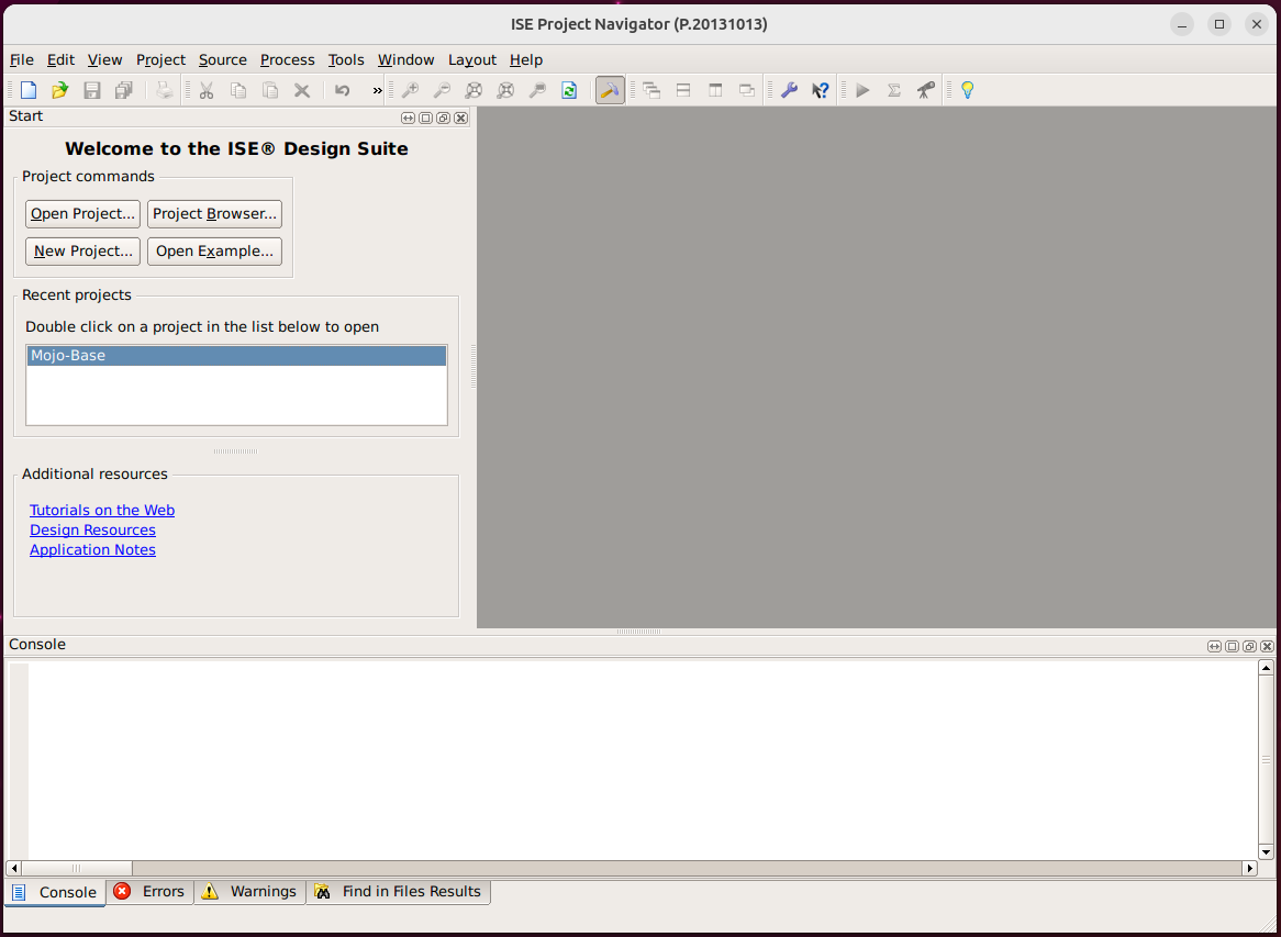
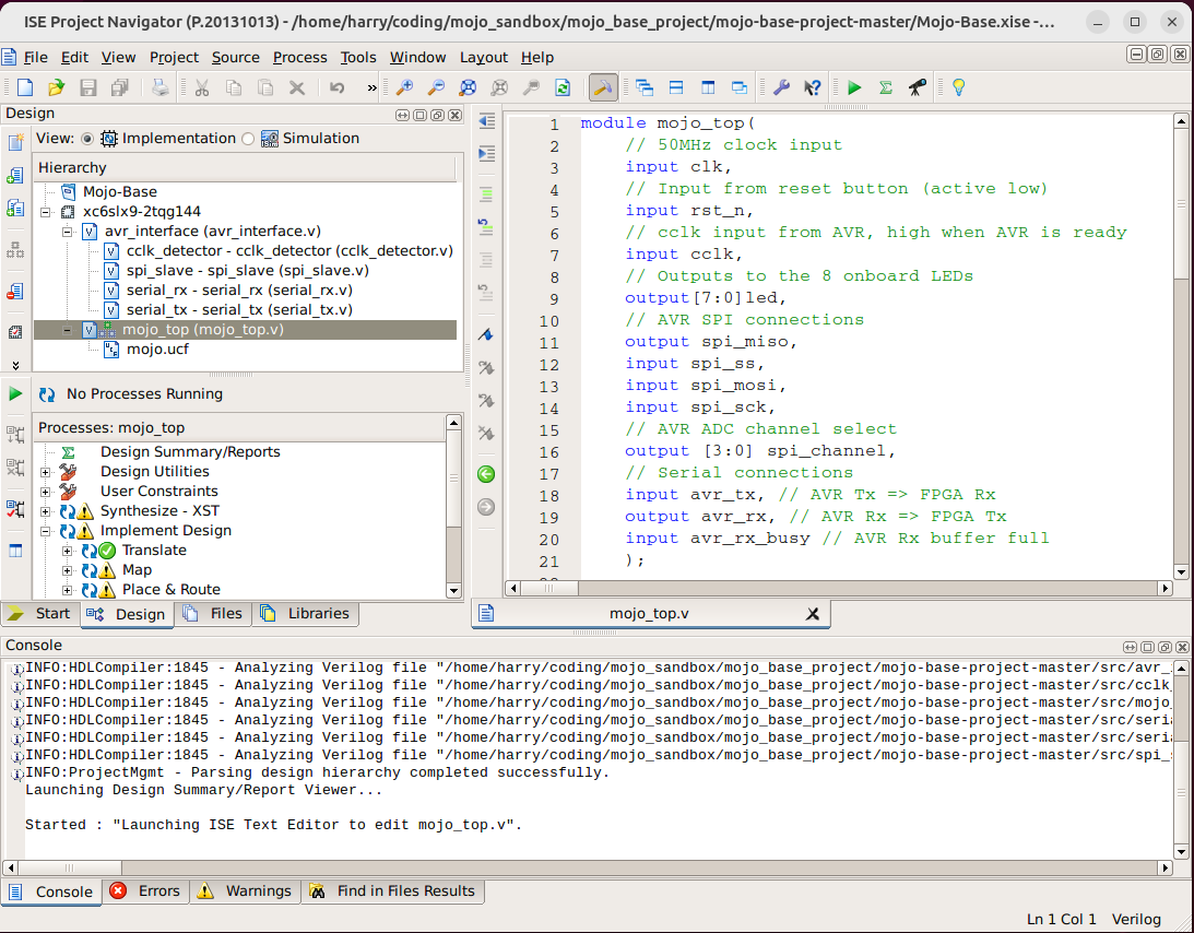
Clone this repo, open it using the File -> Open Project… in the ISE, and select the Mojo-Base.xise file.
You should now have something that looks like this:
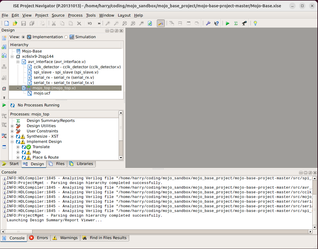
In the ‘Hierachy’ window at the top left, open the mojo_top.v file:
Since I’m just interested in showing you how to compile a bitstream for the Mojo and get it onto the board, we’re not going to go into any details of what is actually in this file. It’s in Verilog, a hardware design langauge that you can think of as kind-of-like-programming-but-not-really.
For now, we’ll just replace the contents with the following that should blink some LEDs:
module mojo_top(
    // 50MHz clock input
    input clk,
    // Input from reset button (active low)
    input rst_n,
    // cclk input from AVR, high when AVR is ready
    input cclk,
    // Outputs to the 8 onboard LEDs
    output[7:0]led,
    // AVR SPI connections
    output spi_miso,
    input spi_ss,
    input spi_mosi,
    input spi_sck,
    // AVR ADC channel select
    output [3:0] spi_channel,
    // Serial connections
    input avr_tx, // AVR Tx => FPGA Rx
    output avr_rx, // AVR Rx => FPGA Tx
    input avr_rx_busy // AVR Rx buffer full
    );

wire rst = ~rst_n; // make reset active high

// these signals should be high-z when not used
assign spi_miso = 1'bz;
assign avr_rx = 1'bz;
assign spi_channel = 4'bzzzz;

//assign led = 8'b0;

reg [23:0] clk_div; // 25-bits of storage
reg [7:0] led_state;
assign led = led_state;
reg dir;

initial begin
	led_state = 8'b11;
	dir = 0;
end

// Clock divider tick
always @ (posedge clk) begin
	clk_div <= clk_div + 1;
end

always @ (posedge clk_div[23]) begin
	if (!dir) begin
		led_state = led_state << 1;
		if (led_state[7]) begin
			dir = 1;
		end
	end else begin
		led_state = led_state >> 1;
		if (led_state[0]) begin
			dir = 0;
		end
	end
end

endmodule
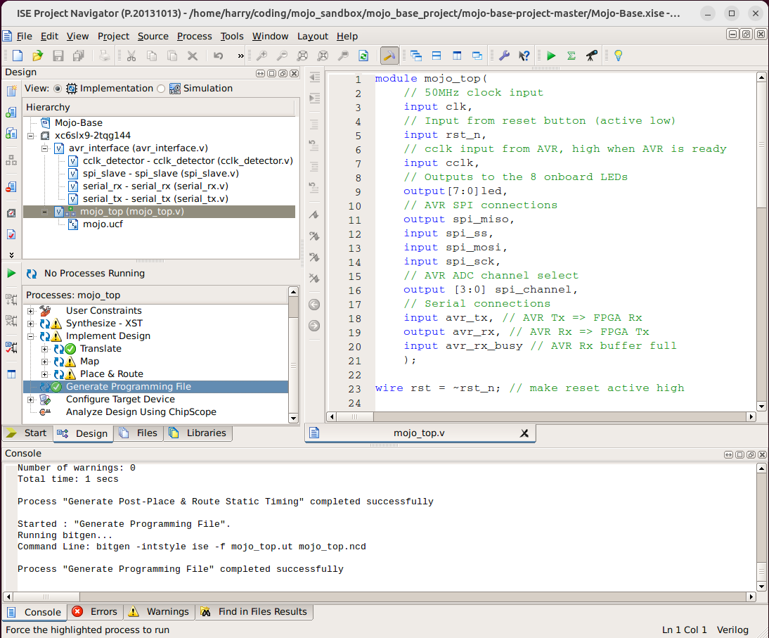
There should be some activity for a few seconds and then a green tick will appear next to “Generate Programming File”. In the directory this project is in there should be a subdirectory called ./syn (for synthesis), and there should now be a file called mojo_top.bin in this directory. This file is a bitstream that we are going to load onto the Mojo in the following section.
Load your design onto the board
It took me a little searching to figure out how to do this. You need to understand that the FPGA itself does not ‘store’ its configuration - all of its internal memory is volatile. On power-up another chip on the board (I think this is the ATmega16U4) which does have non-volatile memory reads out the contents of that memory to the FPGA. This chip (the ATmega) is configured to interpret certain serial commands as instructions to wipe its flash memory and to write other bytes to that memory.
Fortunately I managed to locate this repo from Embedded Micro (they later became Alchitry) which has a Java application to load a bitstream onto the Mojo. Unfortunately I struggled to get this to build. It seems to assume it’s being built in Eclipse, and it’s trying to offer both a GUI and a commandline interface.
For these reasons I decided to re-write the loading logic in python. You can get it here. This should make loading our design onto the Mojo very straightforward. I’m going to assume you’ve done the following:
- Built the
mojo_top.binbitstream using the instructions in the previous section. - Attached the Mojo to your computer via a USB cable and identified the serial port. In my case this is
/dev/ttyACM0. - Cloned this repo and set up a python environment with
serialandtqdminstalled.
Loading the Mojo should then be as simple as running
python3 ./mojo-loader.py [port name] [bitstream filename]
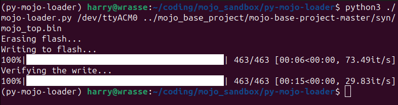
The ‘verifying’ step may hang for a few seconds at the end, that’s normal. If you get any error messages, try unplugging and re-attaching the Mojo’s USB cable. It seems to reset it.
And that should be it. You should now see the Mojo’s built-in LEDs blinking in the following pattern: